
Assembly placement rules (ASM)
The ASM rules are the assembly-level geometric checks: where a die may sit, how far it must stay from its neighbours, and where the interposer’s attachment geometry is allowed to land relative to a die.
There are 4 of them. They live in a single deck,
klayout/drc/rule_decks/8_1_assembly.drc, and they are written entirely
against abstract inputs: the deck contains no layer number, no PDK name and no
technology assumption. See Architecture for why that boundary is
drawn where it is, and Adapter contract for how an adapter
supplies the concrete geometry.
The rule set
Rule |
Check |
Parameter |
Default |
Unit |
|---|---|---|---|---|
ASM.a |
Chiplet boundaries must not overlap |
none (geometric) |
||
ASM.b |
Min. chiplet-to-chiplet spacing is 50 um |
ASM_b |
50 |
um |
ASM.e |
Min. chiplet area is 10000 um2 |
ASM_e |
10000 |
um2 |
ASM.f |
Chiplet-attachment geometry overlapping a chiplet must be fully inside it |
none (geometric) |
Defaults come from config/rule_params.json (registry version
0.2.0). Rules with no parameter are purely geometric: there is no
number to configure, and no adapter can change what they mean.
What the rules see
The deck evaluates two inputs and nothing else.
chiplet_boundaryThe mechanical outline of every placed chiplet. It is not a fabrication layer.
layers_def.drcbuilds it by inserting one polygon per entry of the boundary manifest’sboundariesarray, converting eachpolygon_dbupoint list into anRBA::Polygon. The manifest is passed to the deck as-rd manifest=<path>and is described in Boundary manifest.chiplet_attachment_inputThe region the interposer offers for chiplet attachment, declared by the active interposer adapter. On the IHP IntM4TM2 interposer the adapter derives it from the Cu-pillar geometry,
polygons(9, 35).and(polygons(41,
35))
. On a different interposer it could be a solder-bump region or a hybrid-bonding pad array. The rules never ask which.
Note
Because the boundary travels in a manifest, nothing inside a die can
accidentally look like a chiplet boundary to the checker. The historical
exchange0 190/0 path is reachable only through --legacy-exchange0.
The rules
Each rule is given below with the deck source that implements it. The four panels of the figure show, in plan view, the case each rule is meant to catch and the neighbouring case it is meant to leave alone.
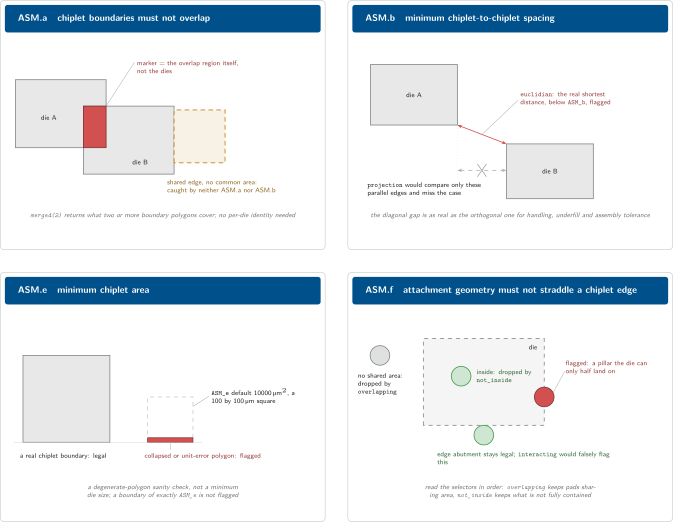
What each ASM rule fires on. The marker geometry is shown in red; the cases that are deliberately legal are shown in green.
ASM.a: chiplet boundaries must not overlap
asm_a = chiplet_boundary.merged(2)
asm_a.output('ASM.a', 'ASM.a : Chiplet boundaries must not overlap')
merged(2) is a merge with a minimum wrap count of two: it returns only the
regions of the layer that are covered by two or more input polygons. Applied
to a layer that holds one polygon per placed die, that is precisely the set of
mutual footprint overlaps.
Three properties of this formulation are worth understanding.
The marker geometry is the overlap itself, not the offending dies. When you open the report you see the exact area in conflict, which is usually what you need in order to decide how far to move a die.
It needs no per-die identity. The check is symmetric and works on a merged, anonymous region, which is why the deck can afford to throw die identity away when it builds
chiplet_boundary.It requires area overlap. Two boundaries that share an edge with no common area are not covered twice anywhere, so ASM.a produces nothing for them.
Warning
Exactly abutting boundaries are caught by neither ASM.a nor ASM.b.
chiplet_boundary is a KLayout Region, which has merged semantics, so
two boundaries that touch along an edge are fused into a single polygon
before either rule sees them. There is then no doubly-covered area for
ASM.a and no inter-polygon space for ASM.b, and a zero-clearance
placement passes silently. A gap of any non-zero width is reported normally.
Treat a clean report as evidence about separated dies, not about touching
ones, and check abutment separately if your flow can produce it.
ASM.b: minimum chiplet-to-chiplet spacing
asm_b_value = drc_rules['ASM_b'].to_f
asm_b = chiplet_boundary.space(asm_b_value.um, euclidian)
A single-layer spacing check between chiplet boundaries, with the default value
taken from drc_rules['ASM_b'] and reported in the rule description string so
the number appears in the report next to the marker.
The metric is euclidian, not projection. Euclidean spacing measures the
true shortest distance in every direction, so a diagonal corner-to-corner gap
between two dies counts as a violation when it is below ASM_b, even though
no pair of parallel facing edges is close. Projection spacing would ignore that
case. For a placement rule whose purpose is to leave room for handling,
underfill and assembly tolerance, the diagonal gap is as real as the orthogonal
one, so the stricter metric is the correct one.
Tip
ASM.b is the only ASM rule with a clean KiCad equivalent. The DRU generator
emits it as a courtyard_clearance constraint so that the interactive
KiCad session and the batch KLayout run enforce the same number. See
KiCad DRU generation.
ASM.e: minimum chiplet area
asm_e_value = drc_rules['ASM_e'].to_f
asm_e = chiplet_boundary.with_area(nil, asm_e_value.um2)
with_area(min, max) selects the polygons whose area lies in the half-open
range from min up to but not including max. Passing nil for min
leaves the range unbounded below, so every boundary under ASM_e is selected
however small it is, which is exactly what a sanity check wants: the smaller the
polygon, the more certainly it is an artefact. Because the range is half open, a
boundary of exactly ASM_e is not flagged.
Note
ASM.e is a degenerate-polygon sanity check, not a real minimum die size. Nothing in packaging forbids a small die. What the rule catches is a boundary that cannot correspond to a physical chiplet at all: a manifest entry with a collapsed or near-collapsed polygon, a unit error that shrank a footprint by three orders of magnitude, a placeholder outline that was never filled in. The default of 10000 um2 is a 100 um by 100 um square, which is far below any die the flow actually handles and far above any artefact of a broken producer. Do not read it as a manufacturability limit.
ASM.f: attachment geometry must not straddle a chiplet edge
asm_f = chiplet_attachment_input.overlapping(chiplet_boundary)
                                .not_inside(chiplet_boundary)
Read the two selectors in order.
overlapping(chiplet_boundary)Keeps the attachment polygons that share area with some chiplet boundary. Attachment geometry lying wholly outside every die, for example a pillar on a part of the interposer that carries no chiplet, is dropped here and never reaches the second selector.
not_inside(chiplet_boundary)Of what survives, keeps the polygons that are not entirely contained in a boundary. Attachment geometry fully under a die is legal and is dropped here.
What is left is exactly the pathological case: an attachment feature that is partly under a die and partly outside it, straddling the boundary edge. That is a pillar or bump the die can only half land on.
The choice of overlapping over interacting is deliberate and is the
easiest thing on this page to get wrong. interacting also selects polygons
that merely touch the other region. An attachment pad placed immediately
outside a die, sharing the die’s boundary edge but with zero common area, would
therefore survive interacting and then fail not_inside, producing a
false ASM.f violation on a perfectly legal layout. overlapping requires
common area, so pure edge abutment stays legal, which is what the rule’s own
definition says. The ADK regression suite pins this behaviour with a fixture
whose pad shares the chiplet’s right edge and lies entirely outside it, and
asserts that ASM.f does not fire.
There is no ASM.c and no ASM.d
The shipped deck contains exactly ASM.a, ASM.b, ASM.e and ASM.f. The gap in the lettering is not an omission in this documentation and not a set of rules waiting to be implemented.
The ADK rules were generalised from an assembly deck that lived inside the
interposer technology, where the letters ran consecutively. Two of those rules,
c and d, were removed during that generalisation, and the surviving
rules kept their original letters instead of being renumbered.
Keeping them has a practical benefit worth knowing about even though the gap
itself is only inherited: a rule name is an identifier that leaves the ADK. It
appears as the category of every entry in the .lyrdb report, in regression
fixtures, and in anything downstream that parses a report or maintains a waiver
list. Renaming ASM.e to ASM.c would change the meaning of every stored
reference to both names without changing any geometry.
Note
If you are comparing against older presentation material or papers, note
that some of it lists ASM.c and ASM.d. Those descriptions predate the
current deck. klayout/drc/rule_decks/8_1_assembly.drc is authoritative.
Single-tier limitation
chiplet_boundary is a flat 2D region. The boundary manifest records
placement polygons with no z coordinate, and layers_def.drc inserts every
polygon into one region with no per-die identity retained.
The consequence is that ASM.a flags any XY overlap between chiplet
boundaries, including the case of two dies legally stacked at different
heights in a multi-tier assembly. The assumption is baked into the manifest data
model, not just into the rule, so lifting it would need all of: a z-aware
manifest schema and therefore a schema version bump, per-die identity carried
through layers_def.drc, and a tier-aware ASM.a. The KiCad-side mirror,
native courtyard collision, is equally 2D.
This is not a practical constraint today: nothing in the toolchain produces multi-tier assemblies. It is recorded here so that the day someone does, the failure is understood rather than debugged.
A second, related boundary: per-die z consistency is not an ASM rule at all. It
is enforced at export time by openroad/chiplet2dbx.py and re-verified by
OpenROAD’s check_3dblox, so an assembly that is never exported gets no
automated z check. See OpenROAD 3Dblox export.
Where the numbers come from
Parameter |
Meaning |
Default |
Unit |
|---|---|---|---|
ASM_b |
Minimum spacing between chiplets, in micrometres. Edge-to-edge between adjacent chiplet boundary polygons. |
50 |
um |
ASM_e |
Minimum chiplet area, in square micrometres. Chiplet boundary polygons below this threshold are flagged. |
10000 |
um2 |
ASM_b and ASM_e are engineering defaults, not foundry-sanctioned
rules. There is no recorded provenance for either value: no layout-rule
document section, no assembly-house specification, no qualification data. They
are round numbers chosen to be safely loose for the assemblies the flow
currently produces, and they exist so that the checker has something to check
rather than because a process demands them.
Treat them accordingly. If you have a real number for your assembly process, it
belongs in an interposer adapter, which may override any entry of drc_rules:
# in pdk_adapters/interposer/<your_interposer>.drc
drc_rules['ASM_b'] = 30.0   # tighter chiplet spacing for this interposer
Both consumers pick the override up, so the two toolchains agree on what they are checking. Keep overrides to plain numeric literals: the KiCad side parses them out of the adapter file textually and silently ignores a computed expression. See KiCad DRU generation.
The shipped intm4tm2 adapter overrides neither value; an IntM4TM2 run
therefore checks the registry defaults.
Note
The situation is different on the interconnect axis. The IXN_* defaults
do trace to a published Cu-pillar table and are documented as such in
Interconnect rules (IXN). Do not generalise the provenance of one axis to
the other.
Running these rules
The ASM rules run on every assembly DRC invocation; there is no flag to select them and no way to disable one. See Running the assembly DRC for the runner, and Verification stages for where the assembly stage sits relative to the interposer’s own DRC.