
Interconnect rules (IXN)
The interposer axis says where chiplet attachment can land. The interconnect axis says how dense, by what method: the bump-to-bump pitch and spacing limits that are a property of the bumping method (Cu pillar, solder bump, microbump) rather than of the substrate underneath it. Those two things change independently in real projects, so the ADK keeps them on separate adapter axes.
The IXN rules implement the second axis. They live in
klayout/drc/rule_decks/8_2_interconnect.drc and, like the ASM rules,
reference no layer number and no PDK name.
The axis is optional and additive
This is the most important property of the axis, and it is enforced structurally rather than by convention.
adk_assembly.drc builds the rule source as a list of file contents and
evaluates the concatenation once, so that every local variable is shared across
decks. The interposer-only chain is:
[ layers_def.drc, <interposer adapter>, <input validation>, 8_1_assembly.drc ]
Nothing is appended to that list unless the axis is switched on, and the two
appends have different conditions. The interconnect adapter and its
required-key validation are appended only when an interconnect adapter is
supplied. 8_2_interconnect.drc is appended when an interconnect adapter
or a per-method file is present, which is what lets a methods file activate
the axis on its own:
parts << File.read(File.join(rule_decks_dir, '8_1_assembly.drc'))
parts << File.read(File.join(rule_decks_dir, '8_2_interconnect.drc')) if interconnect_adapter || ixn_methods
With neither supplied, the evaluated source, the executed checks and the emitted report are identical to a run of the deck as it stood before this axis existed. Adding the axis cannot change an ASM verdict, and a project that does not use it pays nothing for its existence.
Note
config/interconnect.json is loaded unconditionally, and its absence is
tolerated so that a partial checkout still runs. Loading it has no effect on
an interposer-only run: nothing reads interconnect_rules unless
8_2_interconnect.drc is in the chain.
The rule set
Rule |
Check |
Mode |
Parameter |
Default |
|---|---|---|---|---|
IXN.b |
Min. attachment-point spacing is 40 um |
assembly-global |
IXN_spacing |
40 |
IXN.e |
Min. attachment-point pitch is 75 um |
assembly-global |
IXN_pitch |
75 |
IXN.b.<method> |
Min. attachment-point spacing for the method is the value declared for that method |
per method |
IXN_spacing |
per method |
IXN.e.<method> |
Min. attachment-point pitch for the method is the value declared for that method |
per method |
IXN_pitch |
per method |
IXN.x.<method1>.<method2> |
Min. cross-method spacing (the two methods) is the larger of the two declared spacings |
cross method |
IXN_spacing |
per method |
IXN.b.unclaimed |
Min. attachment-point spacing is 40 um (pads outside every method region) |
pads outside every method region |
IXN_spacing |
40 |
IXN.e.unclaimed |
Min. attachment-point pitch is 75 um (pads outside every method region) |
pads outside every method region |
IXN_pitch |
75 |
There are 7 rule forms. Which of them appear in a given run depends on the mode, and the per-method forms expand to one rule name per method and one per method pair, so the number of rule categories in a report is a property of the assembly, not a constant.
The checked region
ixn_region = (defined?(interconnect_region) && !interconnect_region.nil?) \
             ? interconnect_region : chiplet_attachment_input
By default the IXN rules run over exactly the region the interposer adapter
already declared for the ASM axis. An interconnect adapter may narrow it by
declaring interconnect_region, and may do nothing else geometric: it must
not redeclare chiplet_attachment_input or any fabrication layer, because
those belong to the interposer axis. The fallback exists so that no adapter has
to duplicate a fab layer in order to participate.
The two modes
Assembly-global mode
Selected by supplying an interconnect adapter and no per-method file. The adapter’s three numbers apply to the whole attachment region.
ixn_b_value = interconnect_rules['IXN_spacing'].to_f
ixn_b = ixn_region.space(ixn_b_value.um - ixn_circle_tol, euclidian)
ixn_b.output('IXN.b', "IXN.b : Min. attachment-point spacing is #{ixn_b_value} um")

ixn_pitch_value = interconnect_rules['IXN_pitch'].to_f
ixn_pad_size    = interconnect_rules['IXN_pad_size'].to_f
ixn_e = ixn_region.space((ixn_pitch_value - ixn_pad_size).um - ixn_circle_tol, euclidian)
ixn_e.output('IXN.e', "IXN.e : Min. attachment-point pitch is #{ixn_pitch_value} um")
IXN.b is a euclidean spacing check between attachment points. IXN.e is the pitch check, expressed as a spacing; the conversion is explained below. Both report the configured value, not the converted one, so the marker text names the rule the designer actually violated.
Per-method mode
Selected by supplying --interconnect-methods <gds-stem>.ixn_methods.json.
An assembly may mix interconnect methods of the active interconnect PDK: one
die attaches with a coarse pillar option, another with a finer one. One
interconnect PDK per assembly; what varies per die is the method within it.
The sidecar maps a method id to that method’s IXN_spacing, IXN_pitch,
IXN_pad_size and the list of die instances using it. Its format is described
in Interconnect methods manifest; the numbers in it are derived by the exporter
from the .chiplet assembly’s per-die connection: ids and the
interconnect PDK manifest, which stays the single source of truth for them.
The deck builds one region per method by intersecting the attachment region with the boundary polygons of the dies that use it:
ixn_method_ids.each do |mid|
  dies = ixn_per_method[mid]['dies']
  poly = polygon_layer
  boundary_manifest['boundaries'].each do |b|
    next unless dies.include?(b['instance'])
    pts = b['polygon_dbu'].map { |xy| RBA::Point.new(xy[0].to_i, xy[1].to_i) }
    poly.insert(RBA::Polygon.new(pts))
  end
  ixn_method_regions[mid] = ixn_region & poly
end
Per-method mode therefore requires the boundary manifest: the method
definition names die instances, and only the manifest knows where those dies
are. It cannot be combined with --legacy-exchange0, which carries no per-die
instance names, and the runner rejects that combination before spawning KLayout.
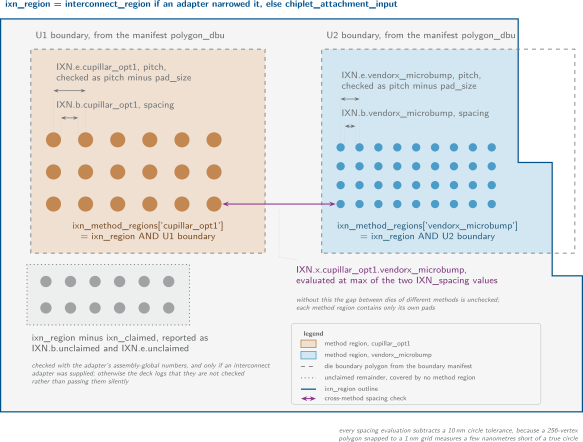
Per-method mode. The attachment region is cut into one region per interconnect method by the boundary manifest, and three families of check run over the pieces.
Three families of check then run.
IXN.b.<method>andIXN.e.<method>The same spacing and pitch checks as assembly-global mode, but each with that method’s own numbers and confined to that method’s region. Method ids are iterated in sorted order, so the rule categories in a report are stable across runs.
IXN.x.<method1>.<method2>A cross-method check over every unordered pair of methods, emitted with
separation, which is a two-layer check between the two method regions:ixn_x_value = [ixn_per_method[m1]['IXN_spacing'].to_f, ixn_per_method[m2]['IXN_spacing'].to_f].max ixn_x = ixn_method_regions[m1].separation(ixn_method_regions[m2], ixn_x_value.um - ixn_circle_tol, euclidian)
This exists because the per-method checks are blind to each other. A method region contains only its own pads, so
IXN.b.<m1>never sees anm2pad sitting just across the gap between two neighbouring dies. Without IXN.x, the space between dies using different methods would be unchecked.The value used is the larger of the two spacings, which is a deliberate conservative choice rather than a derived number. There is no general answer to “what is the minimum spacing between a Cu pillar and a microbump”: it depends on both processes and on the assembly house. Taking the stricter of the two is guaranteed to be at least as safe as either method alone, and it is honest about being a floor rather than a specification.
IXN.b.unclaimedandIXN.e.unclaimedAttachment geometry that no method’s region covers, computed as
ixn_region - ixn_claimed. These are pads on parts of the interposer that sit under no die at all, or under a die that the methods file does not mention.They are checked with the adapter’s assembly-global numbers, and only if an interconnect adapter was supplied. With a methods file and no adapter, the deck has no number to apply to them, and it says so in the log rather than passing them silently:
ADK: attachment pads outside every method region are not checked on the
IXN axis (no assembly-level interconnect adapter)
Tip
Supplying both an interconnect adapter and a methods file is the useful combination. The methods file gives each die the numbers its own attachment method demands; the adapter provides the fallback floor for everything the methods file does not claim, so no attachment geometry escapes checking.
Why pitch is checked as a spacing
Both modes check pitch like this:
min_space = IXN_pitch - IXN_pad_size
KLayout has no native pitch check. DRCLayer#pitch does not exist in the
KLayout versions the ADK targets, so a centre-to-centre constraint has to be
re-expressed as something the engine can evaluate, and the only natural
candidate is an edge-to-edge spacing.
The identity is exact for pads of exactly IXN_pad_size: for two identical
pads of size d on a pitch p, the edge-to-edge gap is p minus d. For pads
larger than IXN_pad_size the conversion is conservative, in other words
it demands a larger true pitch than the rule states, because the extra pad
width is charged against the gap. For pads smaller than IXN_pad_size the
conversion is permissive: two undersized pads can satisfy the derived spacing at
a true pitch below IXN_pitch.
That asymmetry is acceptable in practice because IXN_pad_size is defined as
the representative pad size of the method, and a pad below the method’s own
opening size is a violation of the interposer’s own pad rules, caught at the
interposer DRC stage rather than here. The important point for reading a report:
an IXN.e marker means the derived spacing was violated, and the marker text
names the pitch that produced it.
Note
This conversion is not an ADK invention. It mirrors what the interposer
technology already does for its own pitch rule, Padc.e in
6_9_copperpillar.drc, down to the same subtraction and the same
conservatism note. Both stages of the two-stage DRC therefore agree on the
method, not only on the number.
The 10 nm circle tolerance
Every IXN spacing evaluation subtracts a fixed tolerance:
ixn_circle_tol = 0.01 # um
Attachment points are round. A circle in a GDS layout is a polygon, and the producers in this flow approximate it with 256 vertices whose coordinates are then snapped to the database grid, typically 1 nm. Both steps lose area: the polygon is inscribed in the true circle, and rounding moves vertices by up to half a grid step. A pad array drawn exactly at the method’s minimum spacing therefore measures a few nanometres short of it once it is geometry, and an untolerated check would report a violation on a layout that is correct by construction.
Ten nanometres is comfortably above the discretisation error at 256 points on a
1 nm grid and far below any spacing the methods use, so it removes the artefact
without weakening the rule in any way a designer could exploit. It is the same
constant, for the same reason, as the interposer deck’s padc_b_tol and
padc_e_tol on the Cu-pillar spacing and pitch checks, and as padc_c_tol
on the Cu-pillar enclosure check.
Fail-loud validation
The IXN axis reads numbers and die names from files that other tools wrote. Every way that input can be wrong is turned into an abort, never into a quiet under-check. There are four layers of it.
- The runner, before KLayout starts
resolve_ixn_methods_pathrequires the file to exist, to parse as a JSON object, to carry"schema": "adk-ixn-methods", and to carry exactly the version the runner supports. A stale or foreign methods file is rejected here rather than by the deck, which reads it blind.- The wrapper, before the rules are evaluated
adk_assembly.drcchecks that every method entry carries all four required keys and names the offending method and key if one is missing. It also raises if a methods file is supplied without a boundary manifest.For the adapter path, the wrapper generates a validation snippet per required key and appends it to the eval chain right after the adapter. Note that
config/interconnect.jsonhas already seeded all three keys before any adapter is evaluated, so in a normal checkout the snippet only fires when that registry is absent; an adapter that omits a key silently inherits the registry default rather than aborting.- Die-instance resolution, in the deck
manifest_instances = boundary_manifest['boundaries'].map { |b| b['instance'] }.compact
referenced_dies = ixn_method_ids.flat_map { |mid| ixn_per_method[mid]['dies'] }.uniq
missing_dies = referenced_dies - manifest_instances
unless missing_dies.empty?
  raise "Per-method interconnect references die instance(s) not in the " \
        "boundary manifest: ..."
end
This one is the subtlest and the most valuable.
instanceis optional in the boundary-manifest schema, and a method’sdieslist is just strings. A boundary that omits its instance name, or a typo in the methods file, would produce an empty or partial method region: that chiplet’s pads would silently fall out of the method they belong to, and the run would report fewer violations than it should. Silent under-checking is the worst failure mode a DRC can have, so the deck refuses to run and prints both the unresolved names and the instances the manifest does contain.- Pitch against pad size
raise "Interconnect method '#{mid}': IXN_pitch (#{ixn_pitch_value}) must " \
      "exceed IXN_pad_size (#{ixn_pad_size})." if ixn_pitch_value <= ixn_pad_size
A pitch not greater than the pad size makes the derived minimum spacing zero or negative, which is a check that can never fail. The same guard exists on the adapter path with a message naming the adapter instead of the method.
Where the numbers come from
Parameter |
Meaning |
Default |
Unit |
|---|---|---|---|
IXN_spacing |
Minimum edge-to-edge spacing between chiplet attachment points, in micrometres. |
40 |
um |
IXN_pitch |
Minimum centre-to-centre pitch between attachment points, in micrometres. Checked as a spacing of (pitch - pad_size) since KLayout has no native pitch check. |
75 |
um |
IXN_pad_size |
Representative attachment-pad size in micrometres, used for the pitch-to-spacing conversion. |
35 |
um |
Unlike the ASM defaults, these have provenance. They come from the bumping vendor’s Cu-pillar table, Table 6.1 of the SG13G2 layout rules, and are its default option, Option 1: a 35 um passivation opening, 40 um minimum space, 75 um minimum pitch.
They were chosen to match the interposer technology’s own defaults rather than
to be independently reasonable. interposer_tech_default.json sets
Padc_a = 35, Padc_b = 40 and Padc_e = 75 from the same table, and
the interposer’s 6_9_copperpillar.drc checks them as Padc.a, Padc.b and
Padc.e. Mapping IXN_pad_size, IXN_spacing and IXN_pitch onto those
three numbers means the interposer stage and the assembly stage of the two-stage
DRC check the same values, so a design cannot pass one stage and fail the other
on the same physical constraint.
The consequence for the coarser options of the table (Option 2 at 40 um opening
and 80 um pitch, Option 3 at 45 um and 95 um) is that a design using them is
checked against the Option 1 floor, exactly as it is at the interposer stage.
That is safe but not exact. Per-option adapters are trivial copies of
ihp_cupillar.drc with the Table 6.1 values for the relevant option, and can
be added when a design needs option-specific checking.
Note
Even with recorded provenance, these are defaults in a preview release. They describe one bumping option of one vendor’s table. Confirm the numbers for your own assembly process before relying on a clean IXN result.
Shipped interconnect adapters
An interconnect adapter is a parameter pack and nothing more: three assignments
into interconnect_rules, no layer and no geometry.
Adapter contract carries the table of shipped adapters, the
ihp_cupillar listing, and what each one is for.
See Adapter contract for the full contract an adapter must satisfy, and Running the assembly DRC for how to select one.