
Interconnect PDK
The interconnect PDK owns the post-fabrication elements that join a chiplet to an interposer: Cu pillars, solder bumps and microbumps. It is a separate repository from the interposer PDK, and that separation is the point of it.
Repository: IHP-GmbH/IHP-Interconnect-IntM4TM2. Apache-2.0, version 0.1.0.
Warning
IHP-Interconnect-IntM4TM2 is a Preview Release. The vendorx_microbump
method it ships is a fictional demonstration vendor, clearly marked as such
in the manifest, and is not a real product.
Why this is a separate PDK
The interposer and the bumping method are supplied by different parties. IHP fabricates the interposer, including the under-bump openings in its passivation. What is attached into those openings is a bumping service, and it does not have to be IHP: the same interposer can be bumped by the current bumping vendor, by another vendor, or by a vendor that does not exist yet.
Folding the bump table into the interposer PDK would encode that choice into the substrate. Every design on that interposer would then inherit one vendor’s geometry, and swapping vendors would mean editing the interposer PDK, which nobody outside IHP can do.
So the split is drawn along ownership, and it is drawn precisely:
Concern |
Owner |
|---|---|
UBM openings |
Interposer PDK. It fabricates them. |
3D bodies |
Interconnect PDK. This repository. |
The rule split follows the same logic. A rule that constrains a single opening against the substrate it is etched into (size, enclosure, distance to the edge seal, allowed shape) is a property of the interposer. A rule that constrains the relationship between two attachment points (spacing, pitch) is a property of the method, because it is the bump geometry and the placement accuracy of the bumping process that set it. The first group stays; the second moved here.
Note
The interposer keeps its own Padc.b and Padc.e copies so that
bump_mirror.py can run a standalone Cu-pillar pre-DRC without the
interconnect PDK present. The values are therefore mirrored across the split,
Padc.b against IXN.b and Padc.e against IXN.e, option by
option: the interposer JSON ships Option 1 (40 and 75 um), which is what
cupillar_opt1 carries here. Nothing checks that cross-repository mirror
automatically, so treat a change to either side as a change to both.
Inside this repository the mirroring is guarded:
interconnect_tests/test_manifest.py asserts that
interconnect_rules.json matches the manifest’s pitch_rules method for
method, and that each IXN_pad_size matches that method’s
fab_params.passiv_opening_um.
The method registry
manifest/interconnect_methods.json is the single source of truth. Its schema
is at manifest/schema/interconnect_methods.schema.json (JSON Schema
draft-07), and the top-level key is schema_version, currently 1.0. The
manifest lives at the repository root rather than under libs.tech/<tool>/
because it is the cross-tool contract of the whole PDK, not the data of one
tool.
Everything else in the repository derives from it: the 3D body generator, the LEF macro generator, the stackup fragments, the standalone DRC deck, and the adapter each method maps to. Tools resolve a method id instead of hardcoding a bump table.
import interconnect_manifest as im

lib    = im.get_connection_library()          # ordered default library
bodies = im.layers_3d("cupillar_opt2")        # [(name, layer, datatype), ...]
rules  = im.pitch_rules("vendorx_microbump")  # {"IXN_spacing": ..., "IXN_pitch": ...}
The reader API in libs.tech/klayout/python/interconnect_manifest.py is
stdlib-only and cached: find_manifest_path, load_manifest,
clear_cache, list_methods, default_method, get_method,
get_layer, layers_3d, get_connection_library,
get_connection_stack, body_diameter, pitch_rules, fab_params and
adapter_for.
Interconnect methods manifest is the normative description of the manifest structure.
Shipped methods
Five methods are defined. The default method is cupillar_opt2.
Method id |
Vendor |
3D bodies |
Body diameter (um) |
In default library |
|---|---|---|---|---|
|
Bumping vendor (IHP) |
|
44 |
yes |
|
Bumping vendor (IHP) |
|
49 |
yes (default) |
|
Bumping vendor (IHP) |
|
54 |
yes |
|
Bumping vendor (IHP) |
|
80 |
yes |
|
VendorX (demonstration, non-IHP) |
|
40 |
no |
The default_connection_library is the ordered list emitted into a
.chiplet file when no explicit choice is made: cupillar_opt1,
cupillar_opt2, cupillar_opt3, sbump_sac305. vendorx_microbump is
defined but deliberately excluded from it, because it exists to prove that a
non-IHP method drops onto the same IHP interposer, not to be picked by default.
Parameters per method
Each method carries a connection stack (the physical bodies, bottom to top), the fabrication parameters it needs from the interposer, and its pitch rules.
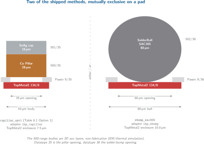
Two of the connection stacks, cupillar_opt1 and sbump_sac305.
They are alternative methods rather than one stack with an optional ball: each
lands in its own passivation opening, draws its own bodies and resolves to its
own adapter. A stack’s total height is what makes a mounted die’s z value
verifiable.
Method |
Connection stack (material, height, diameter in um) |
Passivation opening (um) |
TopMetal2 enclosure (um) |
|---|---|---|---|
|
Cu 28.0 x 44.0, then SnAg 16.0 x 44.0 |
35.0 |
7.5 |
|
Cu 32.0 x 49.0, then SnAg 16.0 x 49.0 |
40.0 |
7.5 |
|
Cu 42.0 x 54.0, then SnAg 19.0 x 54.0 |
45.0 |
7.5 |
|
SAC305 80.0 x 80.0 |
60.0 |
10.0 |
|
Cu 18.0 x 40.0, then SnAg 6.0 x 40.0 |
35.0 |
7.5 |
Method |
|
|
ADK adapter |
|---|---|---|---|
|
40.0 |
75.0 |
|
|
40.0 |
80.0 |
|
|
50.0 |
95.0 |
|
|
70.0 |
130.0 |
|
|
15.0 |
50.0 |
|
Note
The three cupillar_opt* methods all map to the single ihp_cupillar
adapter, so the adapter set is deliberately smaller than the method set. The
adapter is a parameter pack for the ADK rule deck; the manifest is where the
per-option numbers live. When an assembly uses several options at once, the
per-method sidecar carries each option’s own numbers and the ADK emits the
per-method IXN variants. See Interconnect rules (IXN).
The Cu-pillar numbers trace to the bumping vendor’s Cu-pillar table (Table 6.1 of the SG13G2 layout rules, options 1 to 3), which is worth stating because it is not true of every default in the toolchain.
Fabrication anchors
A method does not name interposer layers directly. It names a fab anchor, and the anchor records which interposer, which ADK attachment adapter, and which UBM layers the method lands on:
Anchor |
Attachment adapter |
Layers |
|---|---|---|
|
|
|
|
|
|
This indirection is what makes vendorx_microbump possible without touching
anything else: it reuses ihp_cupillar_anchor, that is, it lands in the same
openings the IHP interposer already fabricates, and changes only the bodies and
the pitch rules.
The 3D auxiliary layers
The bodies are drawn on a dedicated layer range that is not a fabrication range. These are post-passivation physical volumes for 3D rendering, EM simulation and thermal analysis.
Name |
Layer |
Datatype |
Material |
Purpose |
|---|---|---|---|---|
|
500 |
35 |
Cu |
Cu pillar body |
|
501 |
35 |
SnAg |
SnAg solder cap |
|
502 |
36 |
SAC305 |
SAC305 solder ball |
|
510 |
35 |
Cu |
VendorX microbump Cu post (demonstration) |
|
511 |
35 |
SnAg |
VendorX microbump cap (demonstration) |
Two conventions are load-bearing. Layer numbers start at 500 to stay clear of the IHP SG13G2 upstream layers, which top out at 257 with 195 to 256 unassigned, so a body layer can never collide with a fabrication layer of the chip it sits on. Datatypes follow the interposer’s assembly purposes: 35 for pillar, 36 for solder bump.
libs.tech/klayout/tech/interconnect.lyp gives these five layers their
display properties, with names that say plainly what they are, for example
CuPillar.pillar - 3D aux (Cu body).
The generators
Bump bodies
libs.tech/klayout/python/bump3d_generator.py draws the volumes. It was split
out of the interposer’s bump_mirror.py, and the split is what makes it
generic: callers pass the bodies to draw as (name, gds_layer, gds_datatype)
tuples, so the same code renders IHP Cu pillars or any vendor’s microbump.
add_3d_bodies(layout, cell, body_radius_um, bodies=None,
              with_cap=True, num_points=256)

bodies_for_method(method_id, manifest=None)
bodies=None falls back to the IHP Cu-pillar pair, so the interposer’s
bump_mirror.py reproduces its pre-split output byte for byte. Circles are
discretised at 256 points, matching the CuPillarPad PCell and the tolerances
the interposer’s copperpillar DRC deck assumes. with_cap=False skips cap
bodies, which is what a wafer-level (no cap) test wants.
Bump macros for OpenROAD
libs.tech/openroad/python/bump_lef_generator.py renders a minimal LEF
MACRO with CLASS COVER BUMP, sized from the manifest’s
body_diameter_um:
python3 libs.tech/openroad/python/bump_lef_generator.py cupillar_opt1 TopMetal2
from bump_lef_generator import bump_macro_name, render_bump_lef
lef_text = render_bump_lef("cupillar_opt1", "TopMetal2")
The macro name is deterministic, BUMP_<METHOD_ID_UPPERCASE>, and doubles as
the bump-map cell type.
No static LEF files ship with this PDK. The caller must supply the name of the routing layer the pad port sits on, because that name belongs to the consumer’s technology. OpenROAD requires a bump master’s library to live in the same technology object as the chip that instantiates it, so the same method renders against a different layer name for each die technology. A shipped static LEF would have to guess that name and would be wrong for every technology but one.
Filenames must be unique per method and consumer technology. OpenROAD dedupes LEF libraries globally by filename, so reusing one filename across technologies binds the library to whichever technology loaded it first. The generator does not choose the filename for you; that is the caller’s responsibility, and getting it wrong produces a silent misbinding rather than an error.
3D stackup fragments
libs.tech/chiplet_studio/stackup_fragments/ holds one YAML fragment per
method. Chiplet Studio concatenates the fragments an assembly needs onto the
interposer’s own stackup so the bodies render at the right elevation.
z_reference: attachment_surface

CuPillar:
  index: 500
  type: 35
  z: 0.00
  height: 32.00

SnAgCap:
  index: 501
  type: 35
  z: 32.00
  height: 16.00
The z_reference: attachment_surface declaration is what keeps a fragment
method-pure. Its z values are relative to the surface the interposer stackup
declares as attachment_surface_z, so the same fragment sits correctly on any
interposer that declares one, and no interposer-specific offset is baked into
the method.
Fragments are keyed by method id (cupillar_opt1, cupillar_opt2,
cupillar_opt3, sbump_sac305, vendorx_microbump), which is what lets
each die render with its own option’s heights.
Important
ihp_cupillar.stackup.yaml and ihp_sbump.stackup.yaml are deprecated
adapter-keyed copies, kept only for consumers that still select fragments by
adapter id. They carry family-default heights (a copy of Option 1), and a
consumer that resolves method ids must not let them overwrite a resolved
per-method value. Chiplet Studio implements exactly that policy in one place.
See Chiplet Studio.
The standalone DRC deck
libs.tech/klayout/tech/drc/rule_decks/ carries a small self-contained deck so
the interconnect PDK owns its rules and can be exercised in isolation:
layers_def_3d.drcdefines the 500-range body layers.bump_pitch.drcderives the attachment region from the IHP UBM openings and checks the selected method’sIXN.b(spacing) andIXN.e(pitch).interconnect_rules.jsonholds the values, mirrored from the manifest.
klayout -b -r bump_pitch.drc -rd method=cupillar_opt2 ...
Note
This deck is not the canonical assembly check. The canonical one runs in the
ADK over the abstract chiplet_attachment_input region, which is why it
works on substrates this deck has never heard of. bump_pitch.drc hardcodes
the IHP UBM openings and exists so the rules are testable here. Both convert
pitch to a spacing the same way, min_space = min_pitch - pad_size, because
KLayout has no native pitch check. See Interconnect rules (IXN).
Relationship to the ADK
The ADK assembly DRC is interposer-agnostic and method-agnostic. It reaches the method through a second adapter axis, orthogonal to the interposer axis.
Each method names an adapter in the manifest, and the ADK looks up
pdk_adapters/interconnect/<adapter>.drc. The lookup uses the manifest’s
adapter field, not the method id: cupillar_opt1,
cupillar_opt2 and cupillar_opt3 all resolve to ihp_cupillar. The ADK
ships three interconnect adapters, ihp_cupillar.drc, ihp_sbump.drc and
vendorx_microbump.drc, each of which is a parameter pack that declares no
fabrication layer at all.
A design selects the method in its assembly file:
interconnect:
  adapter: "vendorx_microbump"
with connection: vendorx_microbump on each die that uses it. The orchestrator
forwards --interconnect-adapter to the ADK DRC, and hyp_to_gds emits the
matching bodies and connection stack from the manifest.
libs.ref/interconnect_examples/vendorx_on_intm4tm2/ is the demonstration of
what that buys. Two pads at 50 um pitch on real IHP interposer UBM openings, with
VendorX bodies on 510/511. The ADK assembly DRC runs twice over the
same geometry with the same interposer adapter, changing only
--interconnect-adapter:
|
Rule numbers |
Verdict |
|---|---|---|
|
15 / 50 um |
pass |
|
40 / 75 um |
fail ( |
The interposer is untouched; the method decides the verdict. Adding or swapping a vendor needs no code change, only manifest data plus an adapter file.
What INTERCONNECT_PDK_ROOT provides
Consumers locate this repository through three tiers, in order, implemented in
find_manifest_path():
$INTERCONNECT_PDK_ROOT/manifest/interconnect_methods.json.The repository’s own
manifest/, three levels up from the Python module.A parent-directory walk for a sibling checkout named
interconnect_pdk/orIHP-Interconnect-IntM4TM2/that contains amanifest/directory.
The sibling walk accepts both the canonical name and the default clone name, so a
plain git clone resolves without a rename. The environment variable still
takes precedence:
git clone git@github.com:IHP-GmbH/IHP-Interconnect-IntM4TM2.git
export INTERCONNECT_PDK_ROOT="$PWD/IHP-Interconnect-IntM4TM2"
What the rest of the toolchain takes from it:
Consumer |
What it takes |
|---|---|
|
|
|
The method registry: connection stacks written into the |
Chiplet Studio |
The stackup fragments, resolved per method id and offset by the
interposer’s |
ADK assembly DRC |
Nothing directly. It reads the per-method sidecar the exporter writes,
and resolves adapters from its own |
Tip
The visible symptom of a missing interconnect PDK is geometric: pads appear
in the layout and in the 2D view, but no pillar or ball bodies appear in the
3D view. If you see that, check INTERCONNECT_PDK_ROOT before suspecting
the assembly file.
See Interposer PDK (OpenIntM4TM2) for the interposer side of the split and Environment and path discovery for the environment setup.